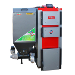
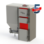
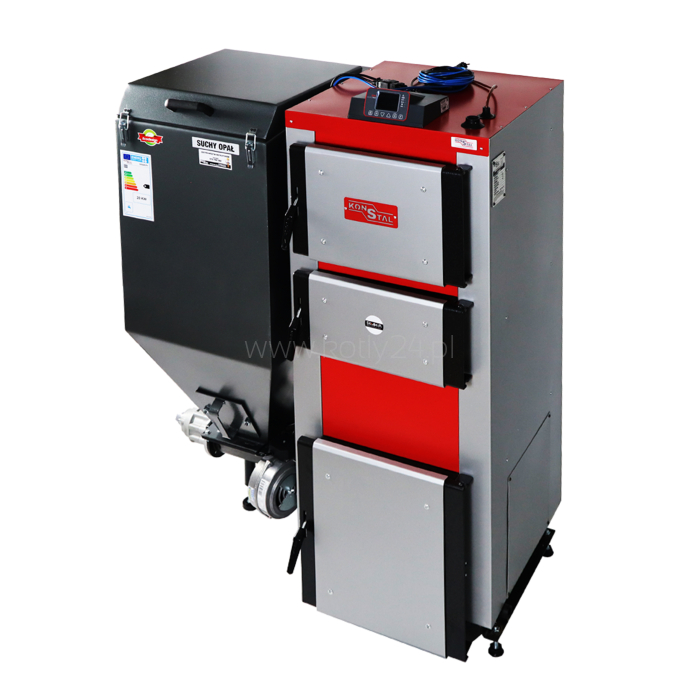
Boiler type SKAM-P+ 13 kW with a feeder for eco-pea coal - type 5th class EcoDesign
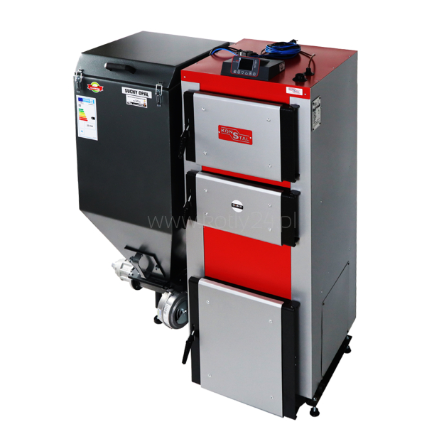
SKAM-P+ boilers are 5th Class and EcoDesign certified. They are equipped with an eco-energy cast iron burner for eco-pea coal, they are extremely durable and trouble-free devices, as well as the OXI Bord microprocessor controller.
- Watch the product:
- Add feedback:
- Code: 0000000395
- Manufacturer: KONSTAL
-
Availability:
 Exists
-
Price history
The lowest price 30 days before the change: 11,792.00 zł gross
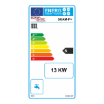
- Energy efficiency class: B
- 13,400.00 zł
- szt.
-
Payment in cash, Payment via bank transfer, eRaty Santander Consumer Bank, Bezpieczny, szybki przelew - Przelewy24, Płatności Ratalne i odroczone
-
Check installments
-
Check installments
The product is shipped within 24 hours.
Parametry techniczne
| Boiler model: | SKAM-P+ |
| Nominal boiler power [kW]: | 13 |
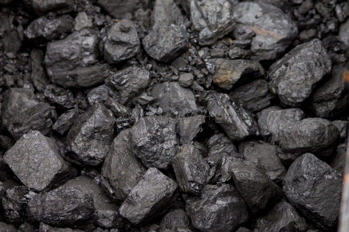
| Basic fuel: | Ekopea coal |
| Area of the heated room [m2]: | 120 |
| Water capacity: | 72 |
| Fuel consumption - max [kg/h]: | 1,6 |
| Flammability max QN [h]: | 75 |
| Chimney draft [mbar]: | 0,11 |
| Flue gas mass flow Load 100%/30% [kg/s]: | 0,0068 / 0,0022 |
| Boiler weight with burner [kg]: | 310 |
| Thermal efficiency [%]: | 91,3 |
| Working pressure [bar]: | 1,2 * |
| Water test pressure [bar]: | 2,5 |
| Fuel mass in the container [kg]: | 120 |
| Charging chamber capacity [liter]: | 96 |
| Charging opening [mm]: | 435x470 |
| max. operating temperature [C*]: | 90 |
| Min. return temperature [C*]: | 55 |
| Min. boiler water temperature [C*]: | 10 |
| Total width [mm]: | 1080 |
| Depth [mm]: | 650 |
| Height [mm]: | 1240 |
| Flue outlet diameter [mm]: | 155 |
| Connections [mm]: | DN 50 (lub na zamówienie) |
| Power supply [A/W]: | 0,22/50 |
| Electric power consumption at 100% power [W/kWh]: | 50/1,2 |
| Electric power consumption at 30% power [W/kWh]: | 20/0,48 |
| Standby power consumption [W]: | 5 |
| Boiler description type SKAM-P+ |
The SKAM-P+ boiler is a structure tested by the accredited laboratory of the Institute for Chemical Processing of Coal in Zabrze and meeting the 5th class according to the PN-EN-303-5:2012 standard and the requirements of ecodesign (ecoproject). With the appropriate certificate, you can apply for funding. The boiler is top-class, which makes its use and cleaning very comfortable. Clean the entire heat exchanger from the front of the boiler. Another advantage is the feeder, which is made entirely of cast iron. It enjoys great popularity and is characterized by trouble-free operation.
The use of a ceramic chamber in the boiler increases the combustion temperature, which allows you to burn off the volatiles. Thanks to this, we obtain additional energy and increase the efficiency of the boiler. This,means its fuel consumption is lowered by 15% per year.
Clean combustion is of great operational importance:
- eliminates precipitation and settling on the exchanger, which is often difficult to remove
removal of soot, which is a product of incomplete combustion of fuels.
- maintains high efficiency of the heat exchanger for a longer period of time.
- boiler cleaning consists in sweeping it out of the beige heat exchanger,
burnt dust
![]() The boiler has a class 5 certificate in accordance with the PN-EN 303-5: 2012 standard and meets the conditions of Ecodesign called Ecoproject
The boiler has a class 5 certificate in accordance with the PN-EN 303-5: 2012 standard and meets the conditions of Ecodesign called Ecoproject
![]() Boiler efficiency above 90%
Boiler efficiency above 90%
![]() possibility of installation in a closed system after installing the cooling coil
possibility of installation in a closed system after installing the cooling coil
![]() Feeder is entirely cast of iron Ekoenergia
Feeder is entirely cast of iron Ekoenergia
![]() 6mm thick sheets
6mm thick sheets
![]() Warranty for the boiler is 5 years, for the controller and the feeding system-2 years
Warranty for the boiler is 5 years, for the controller and the feeding system-2 years
![]() Possibility to connect the Internet module
Possibility to connect the Internet module
What fuel to use?
Basic Fuel

Eco-pea
| Cast iron burner ECOENERGY |
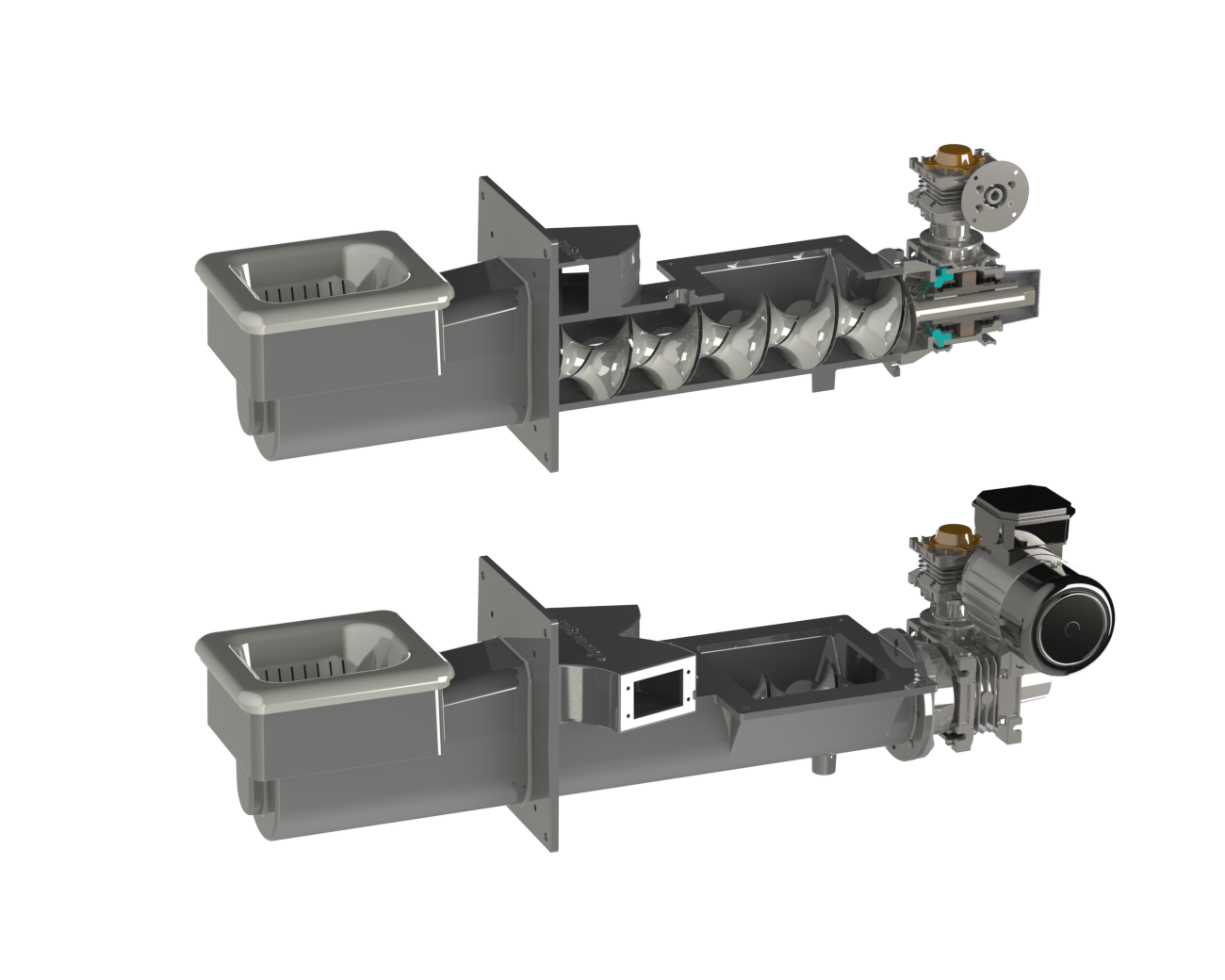
SKAM-P+ boilers are equipped with a cast iron retort burner. The moving elements of the burner are made of ductile iron, which gives it increased resistance to stress. The hearth and the feeding pipe are made of gray cast iron. This burner is characterized by very high resistance to corrosion and high temperature.
| Boiler regulator - IRYD PID controller |

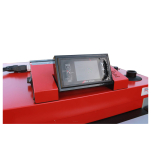
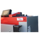
IRYD RTZ Pid Fuzzy Logic COLOR is a regulator designed to control the operation of a central heating boiler with a screw or piston feeder (with a feeder position sensor). The regulator controls an extensive heating installation. A specially designed menu enables gradual activation of subsequent functions and capabilities of the regulator.
This regulator has a special pid fuzzy logic operation algorithm, which, after defining the maximum and minimum boiler power by the user, can smoothly select the appropriate fuel doses depending on the installation load and the type of fuel. The regulator continuously controls the operation of the blower by selecting the appropriate amount of fuel for a given blower speed. In addition, this version is equipped with an additional pid algorithm that influences the flue gas temperature and regulates the boiler power so that the flue gas temperature value does not exceed the maximum value set by the user. These modern control algorithms allow you to save on the amount of fuel burned, and thus it has a beneficial effect on the natural environment. RS 232 ProND communication was used in Iryd RTZ PID RS, which allowed to extend the possibilities of its operation. RS232 ProND allows, among other things, to connect the controller to the LAN module. This communication, compared to 1 - Wire, allowed to increase the scope of functions used for remote control of the regulator.
Funkcje sterownika:

- Smooth blower speed control
- Feeder control with the possibility of retracting when jammed (only available in the case of a piston feeder)
- Control of the central heating circulation pump
- Control of the pump loading the HUW tank
- Control of the second heating circuit - mixer pump or floor installation pump
- Control of the mixing valve actuator
- Control of the circulation pump, which can be used in the hot utility water or central heating circulation circuit
- Support for two REMOTE CONTROLS or room thermostats (two independent circuits)
- The possibility of weather control of the boiler temperature and the mixer circuit*
- Weekly control of central heating circuit, mixer/floor, HUW and HUW circulation
- Operating modes WINTER, SUMMER, HUW PRIORITY, NO HUW
- 5 sets of programmable parameters that can be switched between when using the regulator
- Operation of the bin lid opening sensor
- An algorithm that counts the amount of burned fuel
- Additional pid algorithm monitoring flue gas temperature*
- Antifreeze function below 5°C
- Anti-stop function preventing the pumps from stagnating
*Weather sensor and flue gas sensor must be purchased separately.
| Boiler cross-section type SKAM-P+ |

| Technical data |
|
Boiler type " SKAM P+ " |
SKAM P+ 13 |
SKAM P+ 20 |
SKAM P+ 25 |
SKAM P+ 35 |
SKAM P+ 50 |
|||
|
Rated thermal power |
kW |
13 |
20 |
25 |
35 |
50 |
||
|
Nominal Exhaust Quantity |
g/s |
6,8 |
11,2 |
13,9 |
23,4 |
25,8 |
||
|
Rated flue gas temp |
°C |
91 |
128 |
125 |
121 |
130 |
||
|
Minimum heat output |
kW |
3,5 |
5,2 |
6,8 |
9,9 |
14,4 |
||
|
Minimum amount of exhaust |
g/s |
2,2 |
3,1 |
4,2 |
6,6 |
9,2 |
||
|
Minimum flue gas temp |
°C |
54 |
74 |
66 |
71 |
73 |
||
|
Water flow resistance Δt=20 |
mbar |
0,07 |
0,15 |
0,25 |
0,5 |
1,0 |
||
|
Water flow resistance Δt=10 |
mbar |
0,28 |
0,6 |
1,0 |
2,0 |
4,0 |
||
|
Area of the heated room |
m2 |
do 120 |
120÷220 |
220÷300 |
270÷400 |
400÷620 |
||
|
water capacity |
l |
72 |
90 |
96 |
120 |
167 |
||
|
Fuel usage-max |
kg/h |
1,6 |
2,7 |
3,6 |
5,2 |
6,7 |
||
|
Flammability max QN |
h |
75 |
59 |
44 |
34,5 |
32,8 |
||
|
Chimney draft |
mbar |
0,11 |
0,15 |
0,15 |
0,17 |
0,15 |
||
|
Exhaust mass flow
Load 100%/30% |
kg/s |
0,0068/ 0,0022 |
0,0112/ 0,0031 |
0,0139/ 0,0042 |
0,0234/ 0,0066 |
0,0258/ 0,0092 |
||
|
Boiler weight with burner |
kg |
310 |
530 |
560 |
610 |
700 |
||
|
Thermal efficiency |
% |
91,3 |
92,2 |
88,4 |
90,3 |
91,1 |
||
|
Working pressure |
bar |
1,2* (0,15; 0,2; 0,25) |
||||||
|
Water test pressure |
bar |
2,5* (3,0; 3,5; 4,0) |
||||||
|
Fuel mass in the tank |
kg |
120 |
160 |
180 |
220 |
|||
|
Capacity of the charging chamber |
l |
96 |
128 |
144 |
176 |
|||
|
Feeding opening |
mm |
435x470 |
||||||
|
Max. operating temperature |
°C |
90 |
||||||
|
Min return temperature |
°C |
55 |
||||||
|
Min. boiler water temperature |
°C |
10 |
||||||
|
Overall dimensions max. |
Set width |
mm |
1080 |
1200 |
1520 |
|||
|
Depth |
mm |
650 |
705 |
800 |
840 |
|||
|
eight |
mm |
1240 |
1400 |
1450 |
1550 |
|||
|
Chimney connection |
mm |
Ø155 |
Ø175 |
Ø195 |
||||
|
Connections instal. c.o |
mm |
DN 50 |
||||||
|
Height to the center of the flue outlet |
mm |
1070 |
1245 |
1245 |
1300 |
1327 |
||
|
ZElectric power 230V/50Hz |
A / W |
0,22/50 |
0,35/80 |
0,48/112 |
0,48/112 |
0,45/104 |
||
|
Electric power consumption |
100% ** |
W/kWh |
50/1,2 |
80/1,92 |
90/2,16 |
90/2,16 |
90/2,16 |
|
|
30% |
W/kWh |
20/0,48 |
20/0,48 |
30/0,72 |
30/0,72 |
30/0,72 |
||
|
standby |
W |
5 |
5 |
5 |
5 |
5 |
||
|
* -Standard pressure - Minimum pressure of the water supplying the safety heat exchanger - 2 bar (10 ˚C -15 ˚C) |
||||||||
|
**- Standby power |
||||||||
| Przykładowe schematy podłączenia |
1. A system with a central heating pump and a HUW pump
In this installation, the central heating pump supplies the installation related to space heating. The pump loading the HUW tank heats the water used in the HUW system.

2. A system with a central heating pump supplying radiators, a mixer pump with a mixer controlled by an actuator in the floor heating circuit, a pump loading the HUW tank, a circulation pump in the HUW circulation circuit
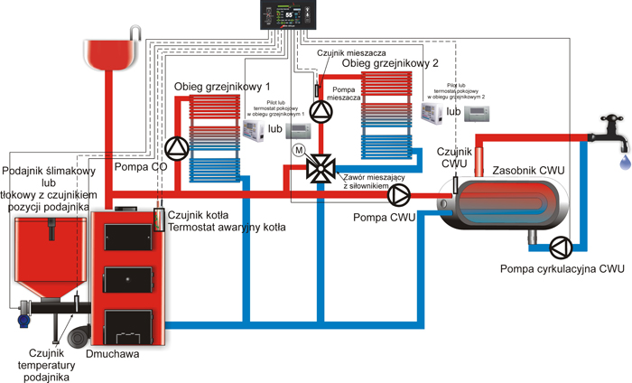
In this system, the central heating pump supplies the heating system with installed radiators. The underfloor installation is powered by a separately regulated circuit consisting of a mixer pump and a mixing valve actuator. The mixing valve can be three-way or four-way. The pump loading the DHW tank heats the water used in the HUW system. The circulation pump works in the HUW circulation circuit, providing hot water in the taps immediately after they are turned on.

3.Installation with a central heating pump, a heating system circuit with a mixing valve actuator, a pump loading the HUW tank, a HUW circulation pump.
In this system, the central heating pump supplies the heating installation with radiators installed in the first circuit. The second radiator circuit is powered by a separately regulated circuit consisting of a mixer pump and a mixing valve actuator. The mixing valve can be three-way or four-way. The pump loading the DHW tank heats the water used in the HUW system. The circulation pump works in the HUW circulation circuit, providing hot water in the taps immediately after they are turned on.
4. Installation with a central heating pump, a floor installation circuit with a manual or thermostatic mixing valve, a pump loading the HUW tank, a HUW circulation pump.
In this system, the central heating pump supplies the radiator circuit. The underfloor installation is powered by a separately regulated circuit consisting of a mixer pump and a manual or thermostatic mixing valve (three-way or four-way). The sensor can be mounted on the return from the floor. If the return temperature reaches the desired value, the floor pump is switched off. The pump loading the HUW tank heats the water used in the HUW system. The circulation pump works in the HUW circulation circuit, providing hot water in the taps immediately after they are turned on.

5.Installation with a central heating pump, a floor installation circuit with a mixing valve actuator, a pump loading the HUW tank, a circulation pump supplying an additional radiator circuit
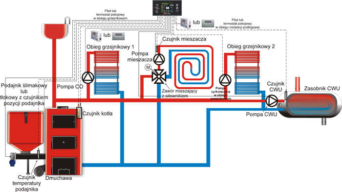
In this system, the central heating pump supplies the installation connected with radiator heating 1. The circulation pump supplies the additional radiator circuit 2, intermittent operation and hours of operation can be set for this pump. The underfloor installation is powered by a separately regulated circuit consisting of a mixer pump and a mixing valve actuator. The mixing valve can be three-way or four-way. The pump loading the DHW tank heats the water used in the HUW system.
6. Installation with a central heating pump, a floor installation circuit with a mixing valve actuator, a pump loading the HUW tank, a circulation pump feeding the plate heat exchanger
In this system, the central heating pump supplies the installation associated with radiator heating. The underfloor installation is powered by a separately regulated circuit consisting of a mixer pump and a mixing valve actuator. The mixing valve can be three-way or four-way. The pump loading the HUW tank heats the water used in the DHW system. The radiator and floor circuit is supplied by a plate heat exchanger. A circulation pump was used to supply the heat exchanger.

7. Installation with a central heating pump feeding the radiators, a mixer pump with a mixer controlled by an actuator in the floor heating circuit, a pump loading the HUW tank, a circulating pump in the HUW circulation circuit, a boiler pump.
In this system, the central heating pump supplies the heating system with installed radiators. The underfloor installation is powered by a separately regulated circuit consisting of a mixer pump and a mixing valve actuator. The mixing valve can be three-way or four-way. The pump loading the HUW tank heats the water used in the HUW system. The circulation pump works in the HUW circulation circuit, providing hot water in the taps immediately after they are turned on. In addition, a boiler pump is used here, which helps to heat the return of the boiler.

8.Installation with a mixer pump and an actuator-controlled mixer in the radiator circuit, a pump loading the HUW tank, a circulation pump in the HUW circulation circuit, and a supporting mixer pump.
In this system, an additional pump was used to support the circulation of the medium in the short circuit of the boiler. If the cross-section of the pipes is insufficient, there are a lot of elbows and narrowings in the system, it is necessary to use such a pump so that when the valve actuator is closed, the medium circulates from the supply to the return of the boiler. In this case, the power supply of the auxiliary pump should be connected in parallel with the power supply of the mixer pump (two pumps should be connected to one "mixer pump" output).

9. Installation with a mixer pump and an actuator-controlled mixer in the radiator circuit, a pump loading the HUW tank, a circulation pump in the HUW circulation circuit, without a supporting mixer pump.
The figure below shows the same system as in point 8, only without the booster mixer pump. In this situation, the cross-section and arrangement of pipes in the short circuit of the boiler (thick pipes in the drawing) must be properly selected by the plumber so as to ensure gravity circulation when the mixer actuator closes the valve completely. If the conditions are not met, there may be a situation where after closing the valve, the boiler return temperature will not increase. In this case, a circulation pump should be used as in point 8.

Ask a question about the product. Our team will be happy to provide a detailed answer to your inquiry.







 Polish